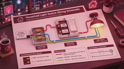
A 1 way light switch wiring diagram is the small planning document that can prevent a large renovation delay. In US electrical terminology, a one-way switch is usually called a single-pole switch: one switch controls one light or group of lights from one location. The work looks simple, but the cable route, box fill, grounding method, and inspection requirements all affect the schedule. Treat this as a planning guide, not permission to work on an energized circuit. Turn off the breaker, verify the circuit is dead with a properly rated tester, and use a licensed electrician when the existing wiring is unclear.
What the diagram needs to show
A useful 1 way light switch wiring diagram identifies four separate functions: line, load, neutral, and equipment grounding conductor. Line is the incoming hot conductor from the panel. Load is the switched hot conductor that continues to the light fixture. Neutral completes the circuit back to the panel and normally connects directly to the fixture. Ground provides a fault-clearing path through the metal box, device yoke, or grounding conductor.
The switch normally interrupts the hot conductor, not the neutral. When the switch is on, power travels from line through the switch and returns to the fixture on the switched-hot wire. When the switch is off, the fixture no longer receives an energized hot connection. Many diagrams show black for hot, white for neutral, red for switched hot, and green or bare copper for ground, but wire color alone is not proof of function. Older work can include repurposed white wires, faded insulation, or undocumented changes.
Before ordering devices, record the box type, cable size, breaker rating, and number of conductors entering the box. A 15-amp circuit commonly uses 14-gauge copper, while a 20-amp circuit commonly uses 12-gauge copper, but the existing installation must be confirmed rather than guessed. Do not install a 20-amp breaker to solve a nuisance trip without verifying the entire circuit.

Two common wiring layouts
The first layout brings power into the switch box. The incoming hot connects to one switch terminal, and a switched-hot conductor leaves the other terminal for the light. Neutral passes through the box and continues to the fixture. This arrangement is easy to understand because the switch box contains line power, load power, neutral, and ground. A diagram for this layout should show every splice, including a pigtail if the incoming hot also supplies another cable.
The second layout brings power to the light fixture first. In that arrangement, the cable carrying line and neutral enters the ceiling or wall box. A two-conductor cable then carries a hot feed down to the switch and a switched-hot return back to the fixture. This is where many renovation mistakes begin. The white conductor used as a hot feed must be reidentified according to applicable electrical rules, and the box may not contain a neutral that is available for a smart switch.
A 1 way light switch wiring diagram should make the power location obvious. Label “power at switch” or “power at light” in the project notes before drywall closes the wall. Take clear photos with a ruler or tape measure in view, and save them in the renovation folder alongside the panel schedule, permit number, and inspection date. If the electrician changes the route, update the diagram immediately instead of relying on memory.
A safe planning sequence
Step 1: Map the circuit. Turn off the suspected breaker and confirm that the light and any nearby receptacles are dead. Check from more than one point if the circuit serves adjacent rooms. A noncontact tester is useful for an initial check, but it should not be your only verification method when conductors are exposed.
Step 2: Photograph before disconnecting anything. Capture the original connections, cable entries, grounding conductors, and box depth. Do not assume two wires that look similar serve the same purpose. If there are aluminum conductors, cloth insulation, knob-and-tube remnants, multiple circuits in one box, or signs of heat damage, stop and bring in an electrician.
Step 3: Match the replacement switch to the circuit. A standard single-pole switch is different from a three-way switch, dimmer, timer, or smart switch. Confirm the device rating, compatible bulb type, minimum load for dimmers, and box space. Smart switches often require a neutral and may need a neutral-compatible configuration.
Step 4: Plan inspection and access. Many jurisdictions require a permit or inspection for new branch-circuit wiring, relocated boxes, or substantial alterations. Ask the building department or your electrical contractor before rough-in. Keep the wall open until the rough inspection is complete if the project requires one.
Step 5: Close the loop. After the work is approved, label the breaker, photograph the final connections, and store the final 1 way light switch wiring diagram with the renovation schedule. If it is not on the schedule, it is not happening; that includes the electrician’s return visit, wall repair, paint touch-up, and final device installation.

Common failure points that create rework
The most common failure is confusing a line conductor with a switched-hot conductor. Both can test hot under different switch positions, so a quick reading does not replace a proper circuit identification process. Another problem is assuming every switch box contains a neutral. Older switch-loop installations often do not. That matters if your fixture plan includes a motion sensor, Wi-Fi switch, or timer.
Box fill is another schedule trap. Each insulated conductor, grounding conductor grouping, cable clamp, and device counts toward the box’s permitted volume under applicable code rules. Adding a dimmer or smart switch can make a crowded box worse because the device body occupies substantial space. A deeper listed box might be needed, which can affect tile, backsplash, plaster, or cabinet clearance.
Loose terminations create heat and intermittent operation. Terminal screws should be tightened according to the device manufacturer’s instructions, and push-in connections should be used only when the device and conductor type permit them. Do not bury junctions behind drywall, and do not leave capped conductors without a reachable box. These shortcuts can turn a five-minute trim task into an inspection failure and a wall-opening exercise.
How to coordinate the trade without losing a day
Send the electrician a short packet before the appointment: the room plan, fixture model, switch model, circuit photos, preferred switch height, and your target inspection date. Mark whether the wall is open, whether insulation is installed, and whether the panel directory is accurate. That allows the trade to bring the correct box, cable, connectors, and device instead of spending the first hour diagnosing conditions that could have been documented.
Use the 1 way light switch wiring diagram during the rough-in walk-through. Ask the electrician to point out where line enters, where the switched leg leaves, where neutral is available, and how grounding continuity is maintained. You do not need to direct technical work, but you do need a record that matches the walls before they close. In a damp Portland basement, moisture control and box protection deserve attention; in a dry Phoenix remodel, heat exposure and brittle insulation can change the inspection conversation.
Final checklist before drywall
Confirm that the correct breaker is identified and labeled. Confirm that the switch is single-pole rather than three-way. Confirm that the box is accessible, properly supported, and large enough for its conductor count. Confirm that all required grounds are bonded and that neutrals are spliced correctly rather than placed on a switch terminal. Confirm that the fixture location, switch height, and cable route match the room plan.
Keep one printed copy of the 1 way light switch wiring diagram in the project binder and one digital copy with the permit photos. Before drywall, compare the drawing with the actual installation and record any change in red ink. After installation, test operation, inspect the trim, and make sure the wall-finishing crew knows the box location. If the circuit behaves unexpectedly, the breaker trips, insulation is damaged, or the diagram does not match what you see, pause the schedule and call a qualified electrician. A controlled delay is cheaper than opening a finished wall.
What does your current diagram show: power at the switch or power at the light, and is the wall still open for an inspection correction?