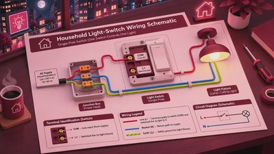
A light with 2 switches wiring diagram sounds like a small renovation task, but it can create a major scheduling problem when the existing cable layout, switch type, and inspection requirements are unclear. Before opening a wall, establish what the switches are supposed to do, where power enters the circuit, and whether the work belongs to a licensed electrician. If it is not on the schedule, it is not happening, and electrical work needs a safer schedule than a rushed Saturday afternoon.
First, define what “two switches” means
Homeowners use “two switches” to describe several different arrangements. Two switches might control one light from opposite ends of a hallway. That setup normally uses two three-way switches, with traveler wires connecting the switches. Alternatively, two switches in one wall box might operate two separate lights. In that case, each switch can have its own switched-hot conductor, while the line side may be shared with a pigtail.
A third possibility is a single-pole switch at each location that controls separate fixtures. Those are not interchangeable layouts. A useful light with 2 switches wiring diagram must match the actual function, not just the number of devices on the wall.
Write the intended result in one sentence before ordering parts: “One ceiling fixture will turn on and off from both hallway locations,” or “The left switch controls the pendant, and the right switch controls the under-cabinet lights.” That sentence prevents a common renovation failure: installing a diagram for two-way control when the project actually needs two independent circuits.
Map the existing circuit before demolition
Start with the project schedule, not the screwdriver. Put these items on the task list:
- Identify the breaker and label it at the panel.
- Confirm power is off with a properly rated tester, then verify the tester on a known live source before and after testing.
- Photograph each box before disconnecting anything.
- Record cable counts, conductor colors, grounding conductors, and which wires were attached to each terminal.
- Mark the fixture location, switch locations, and access points above the ceiling or below the floor.
- Book the electrician and inspection window before drywall closes.
Never rely on insulation color alone. In older homes, a white conductor can be used as a hot conductor and should be reidentified where required. A switch box may also contain more than one circuit, especially after additions or kitchen remodels. Turn off the correct breaker and test every conductor in the box.
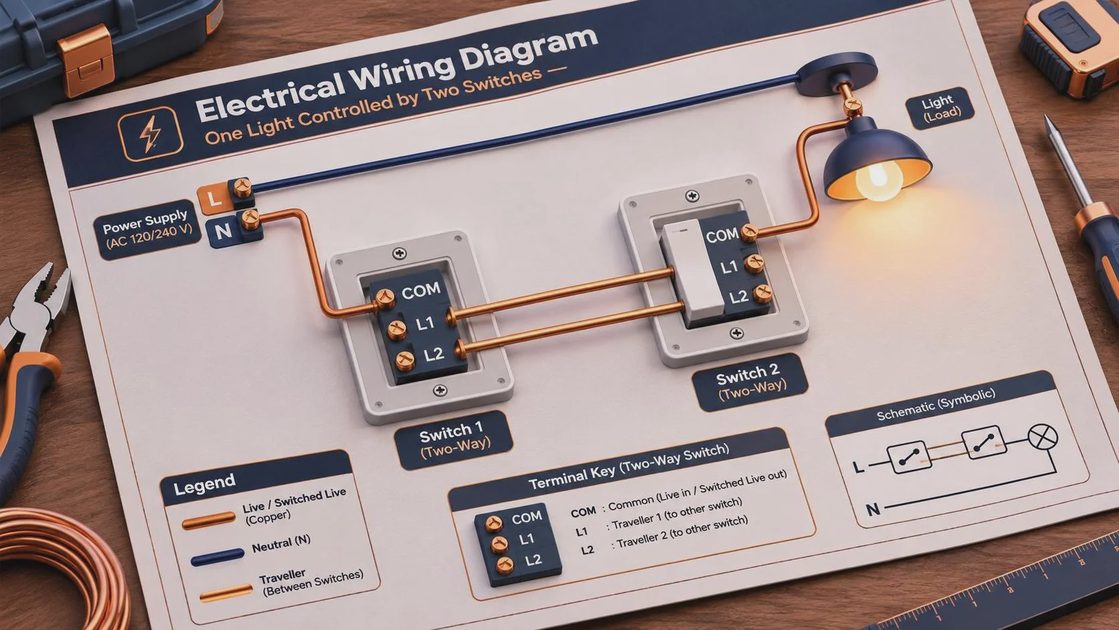
The best documentation is a simple hand sketch with labels such as line, load, neutral, ground, and traveler. Take a second photograph with a tape measure in view so the electrician can estimate cable length and box placement without reopening the wall. This is more useful than a blurry close-up taken after wires have been removed.
How a typical three-way layout is organized
For one light controlled from two locations, power may enter at the first switch, at the light fixture, or at an intermediate junction. The arrangement changes the cable routing, but the functions remain consistent. The line is the incoming energized conductor. The load is the switched conductor going to the fixture. The neutral completes the circuit to the fixture, and the equipment grounding conductor provides a fault path. Travelers connect the two three-way switches and carry the switching relationship between them.
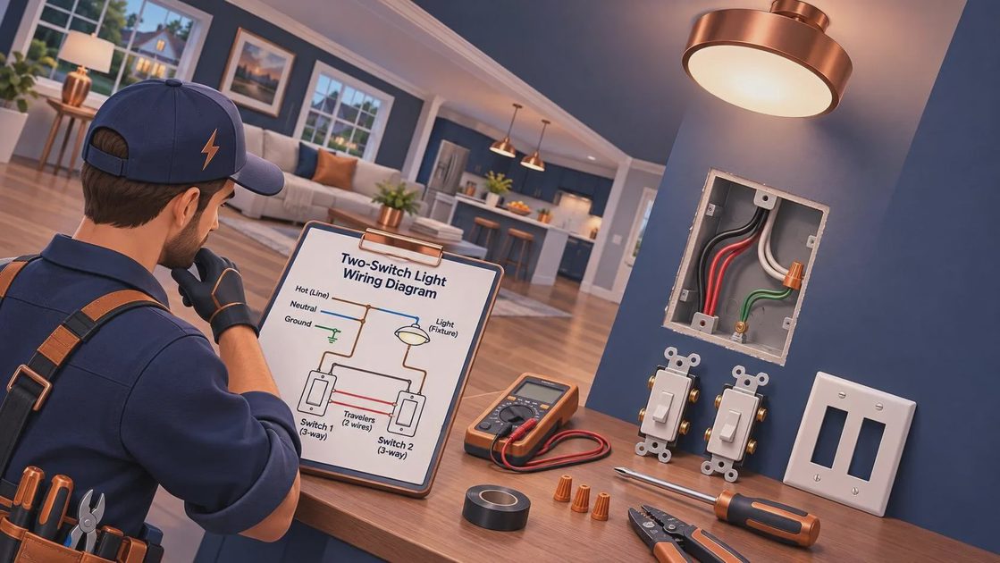
A light with 2 switches wiring diagram should show these functions clearly rather than presenting a vague picture of colored wires. At one three-way switch, the common terminal usually receives the line or the load. The two traveler terminals connect to the corresponding traveler conductors. The second switch receives the other end of that traveler pair, with its common terminal connected to the fixture conductor or incoming line, depending on the circuit layout.
The brass and dark terminal arrangement matters. On many three-way switches, the common terminal is a different color from the traveler terminals. Do not assume a new switch matches the old switch based on screw position. Read the device markings and photograph the original connections before removal.
Where renovation schedules usually fail
The wiring is often not the only problem. A new light fixture may arrive with a canopy that does not cover the old ceiling opening. A replacement switch may require a deeper electrical box. A smart switch may need a neutral conductor in the switch box, while the existing box has only line, load, and travelers. A dimmer may also require compatibility with the lamp or LED driver.
Add these checkpoints to the schedule:
- Confirm the fixture weight and whether the ceiling box is rated to support it.
- Confirm the box fill calculation after adding wires, pigtails, or a larger device.
- Check whether the wall box can accept a deeper switch without crushing conductors.
- Verify that the dimmer or smart switch is rated for the fixture load.
- Order the fixture, switch, wall plate, connectors, and box before the electrician arrives.
- Reserve time for patching and paint after the electrical inspection.
A diagram cannot solve a box that is too small or a ceiling bracket that is not supported. Those are procurement and coordination issues, so treat them as separate tasks rather than discovering them after the circuit is open.
Reading a diagram without copying it blindly
When reviewing a light with 2 switches wiring diagram, compare it with the actual circuit in four passes. First, locate the power source. Second, trace the neutral to the fixture. Third, identify the conductor that reaches the fixture as the switched hot. Fourth, follow the travelers between the switches. If the drawing does not make those paths obvious, do not use it as the work plan.
Many online diagrams show idealized new construction. Your house may have metal boxes, conduit, older cable, a junction above the ceiling, or a switch loop that does not include a neutral at the wall box. A licensed electrician can determine whether the existing wiring is usable, whether conductors need reidentification, and whether local permit rules apply.
Do not work on energized wiring, do not depend on a noncontact tester as your only proof of de-energization, and do not bury a junction box behind finished drywall. If the project requires opening a ceiling or removing insulation, schedule the electrical rough-in before the drywall crew and confirm who is responsible for closing the access afterward.
A practical handoff checklist
Before the electrician arrives, provide a one-page handoff containing the fixture location, switch locations, desired control behavior, breaker label, photos, and a sketch. Note whether the walls are open, whether insulation is present, and when the drywall contractor is scheduled. Include the product model numbers for any smart switch, dimmer, LED fixture, or motion sensor. Compatibility questions are easier to answer before installation than after a return trip.
During the work, ask the electrician to label the panel, confirm the circuit at the box, and explain any change from the original plan. After installation, test both switch positions, the fixture, the dimming range, and any smart-control features. Keep the diagram, product manuals, permit paperwork, and inspection record in the renovation folder.
A light with 2 switches wiring diagram is useful planning evidence, not permission to bypass safety rules. The most efficient project is the one that reaches inspection with the correct parts already on site and no hidden junctions waiting for the next owner to discover. Post your circuit layout, fixture type, and renovation stage in the forum, and ask which trade must be scheduled next.